Versions 1.6.0 and 1.6.1 add four things: a G-code generator for grooving, the real insert shape drawn in the simulator, a searchable ISO tool catalog, and automatic plunge checking before the toolpath runs.
CAM Grooving: toolpath generator for grooves (v1.6.1)
Pick a groove on your DXF contour and get ready-to-run G-code for roughing and finishing. Outer (OD) and inner (ID) grooves, perpendicular and slanted walls, with a live preview throughout.
- Modes: Roughing / Roughing + Finishing / Finishing only.
- OD and ID grooves, perpendicular and slanted walls; corner fillets are handled.
- Peck retract strategies: Full (retract above stock), Short (retract a set distance), None (single plunge to the groove floor).
- Fit warnings before you cut: tool wider than groove floor, groove narrower than shank, allowance issues.
- Live preview of the groove with the tool and the active tip code reference point.
- Presets: save the whole form under a name and reuse it on the next part.
- Grooving tool catalog: Sandvik CoroCut, Iscar, Kennametal plus a generic width × radius grid.
- Generates the same TOOL LIST + tool-change block format as CAM Roughing.
Real insert shape in simulation (v1.6.1)
The simulator no longer shows the tool as a dot. It draws the actual insert shape to scale: a 35° VNMG, 55° DNMG, or 80° CNMG with the correct nose radius, at the exact programmed point, moving along the toolpath.
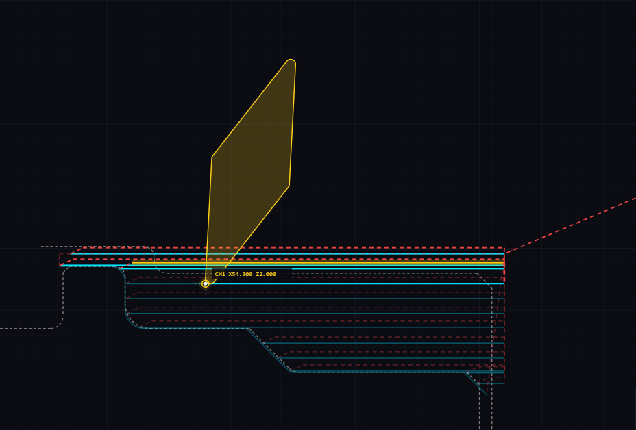
- Enable in Machine Configuration → "Show real insert in simulation" (off by default).
- The insert is read automatically from the program comment (
T0101 (DNMG110404)), the Setup Sheet, or auto-detection. Nothing to configure manually. - Supported shapes: C (80°), D (55°), V (35°), T (60°), S (90°). All generated mathematically from the ISO code, any nose radius.
- Optional tip code P1–P4 in the comment sets the orientation (right/left-hand, OD/ID).
- Dual-turret: both turrets show their own insert simultaneously.
- Programs generated by the CAM module show the correct insert automatically.
Tool catalog: searchable ISO toolholder & insert database
Before v1.6.0, the CAM only knew the nose radius. Now it knows the full holder (approach angle, shank size, relief angle, max ramp angle) and the insert (shape, size, radius, clearance). That's what makes plunge checking, Setup Sheet auto-fill, and the tool list possible.
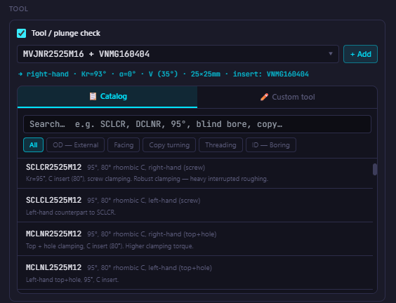
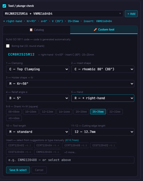
- Searchable catalog of ISO 5611 toolholders. Type anything (
SCLCR,DCLNR,95°,blind bore) and the list filters instantly. - Categories: OD external, facing, copy turning, threading, ID boring.
- Insert database with common turning inserts (C, D, T, V, W, S…); only inserts that fit the chosen holder are shown.
- Boring bar builder (ID): bar diameter, bar length, insert IC. The correct ISO bar code (e.g.
S16R-SCLCR09) is generated automatically. - Custom tool builder: build an ISO 5611 code position by position (shape, Kr, shank, hand) and the code is generated for you.
- Auto-detect unknown inserts: type an ISO code not in the database and the app parses it and offers to save it.
- Saved custom tools are stored permanently (marked ★) and never overwritten by updates.
- Nose radius mismatch warning: if the nose radius in your cutting parameters doesn't match the selected insert, the app warns you.
Plunge check: automatic collision detection
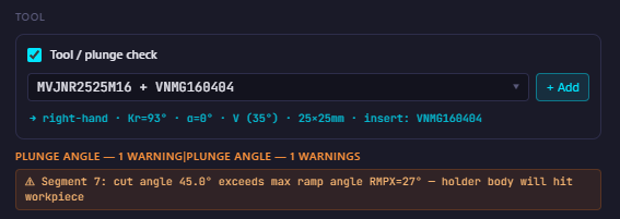
Before the G-code is generated, the app checks whether the selected tool can cut the contour and marks problem segments in red on the drawing. It catches things like the back face of an insert rubbing a shoulder, the holder body hitting the part during diagonal infeed, a nose radius larger than a groove corner, or a shank too wide for the groove.
- Back-face / approach angle (Kr): cutting angle of a segment exceeds the holder's approach angle.
- RMPX (max ramp angle): during diagonal infeed, the holder body would hit the workpiece.
- Nose radius vs. concave arc: groove or corner arc is smaller than the insert nose radius.
- Shank width vs. groove: the groove is narrower than the shank.
- Direction-aware: works for OD and ID tools, Z− and Z+ feed direction. Exit walls are not flagged.
- Flagged segments are drawn red with red dots. The check is a checkbox in the CAM dialog and starts switched off for every new contour.
Tool change block
The CAM writes the complete tool-change block at the start of the generated code. No more adding T0101, spindle mode, and approach moves by hand.
- Set: T number, offset/D, G97 or G96 (RPM or surface speed), M03/M04, approach X and Z, comment text.
- A TOOL LIST accumulates at the top of the program; every generation with a tool change adds a new entry.
- Comments include the holder, insert and nose radius. The Setup Sheet picks these up automatically.
- Dialect-aware:
( )for Fanuc,;for Siemens/Sinumerik. - Regenerate replaces the old block in place. Change one number, regenerate, nothing is duplicated.
Contour range selection
Instead of clicking every segment of a long contour, click the first and last segment and the app selects everything between them along the shortest connected path.