Up to now MultiPath showed the part, stock and toolpaths in 2D. Version 1.7.1 adds a 3D view in which you can watch material being removed, together with the tools and the workholding. The chuck, collet, centres and steady rest are no longer just a picture: they take part in the collision check and appear in the Setup Sheet. All CAM toolpaths for both channels are now kept in one list of operations, and programs with G41/G42 are generated and simulated the way the machine handles them.
3D view
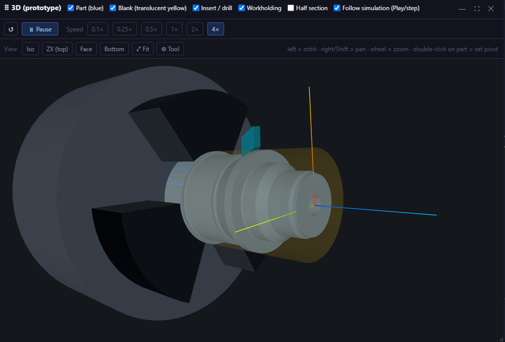
Open the 3D view with the 🧊 3D button in the bar above the canvas or with the 3D icon in the CAM quick menu. It opens in a floating window that you can move anywhere, resize, maximise or minimise. The size and position are remembered, so next time it opens where you left it.
Following the simulation
With Follow simulation (Play/step) on, the 3D view moves together with the simulation and removes material block by block. You can start, pause and step the program and change its speed directly in the 3D window — there is no need to switch back to the 2D canvas.
What is shown
The part is built from its contour and the stock matches the 2D view exactly. Checkboxes in the header switch on and off the part, the translucent stock, the tool and the workholding. Turning inserts, drills and grooving tools are drawn, as well as the chuck with jaws, centres, tailstock and steady rest. Half section cuts the model in half so that bores and internal grooves are visible.
Controls
- Left mouse button rotates the view, right button or Shift pans, the wheel zooms.
- Double-click on the part sets the centre of rotation.
- Buttons switch between preset views: isometric, view from above (the default), face, bottom, fit to window and a view following the tool.
Workholding
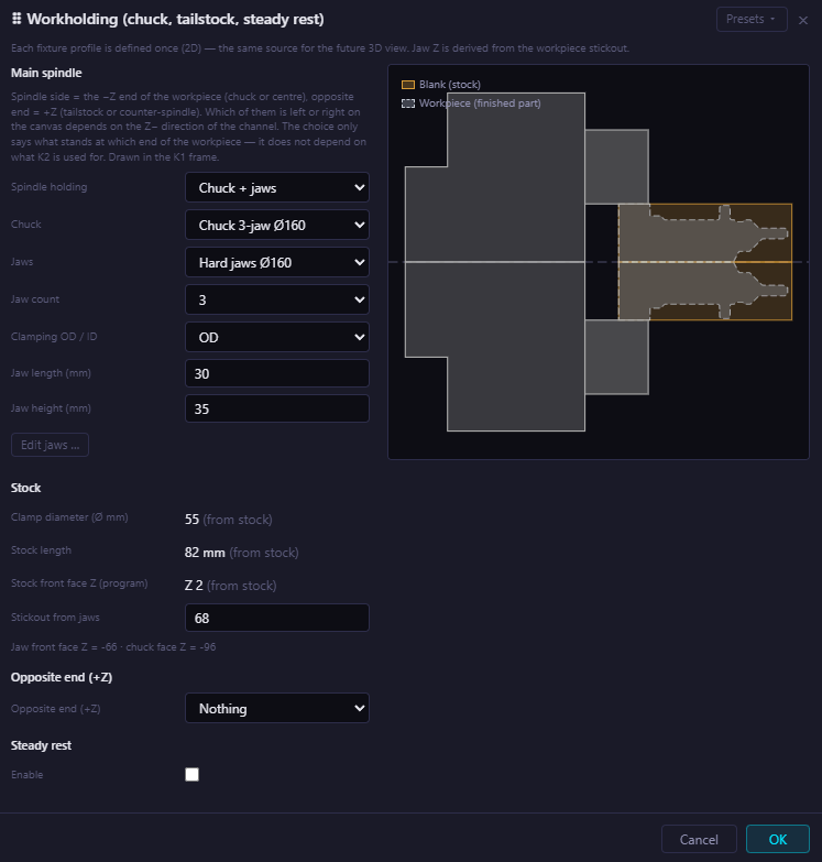
The workholding window is in the CAM menu under ⛭ Workholding / accessories. You describe what holds the workpiece at each end:
- Spindle side: a chuck with jaws, a collet or a centre.
- Opposite end: nothing, a tailstock or the counter-spindle.
- Steady rest: on or off.
The parts can be combined freely — for example a chuck with a tailstock and a steady rest for a long shaft. The clamping diameter, stock length and face position are taken from the stock, so in most cases you only enter how far the stock sticks out. The preview on the right shows the stock, the finished part and the workholding to scale, and a complete set-up can be saved as a preset and reused.
Chuck and jaws
For the chuck you choose the jaws, the number of jaws, OD or ID clamping and the jaw length and height. If the jaws don't fit the chuck, MultiPath warns you, but lets you keep the choice. In the jaw editor you define the individual steps of the jaw and the clamping step — the step on which the jaw actually holds the workpiece.
When clamping in a bore (ID), MultiPath finds the bore in the jaw zone by itself. If there is no suitable bore there, you get a message and enter the diameter manually.
Collet, centres and steady rest
For a collet you only enter the stickout from the collet face. Centres can be used at the tailstock or in the spindle for machining between centres. The position of the tailstock and of the steady rest can be set by clicking on the canvas.
Collisions with workholding
The holder and the insert are checked against the workholding, rapid moves included. Each collision is marked on the canvas and a badge shows how many there are; clicking it jumps to the next one. So you see before the first part whether the tool reaches into the jaws or hits the tailstock.
Setup Sheet
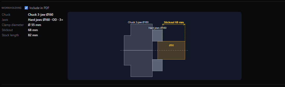
The Setup Sheet has a new Workholding section with the chuck, jaws, clamping diameter, stickout and stock length, plus a dimensioned sketch. The setter can see at a glance how the part is to be clamped. Whether the section is printed is decided by Include in PDF. A sample project with a chuck is installed with the application.
Operations
Every toolpath you create in CAM Turning, CAM Grooving or drilling is now saved as an operation in the Operations panel. The list is saved with the project, so you can come back to any operation later and change it.
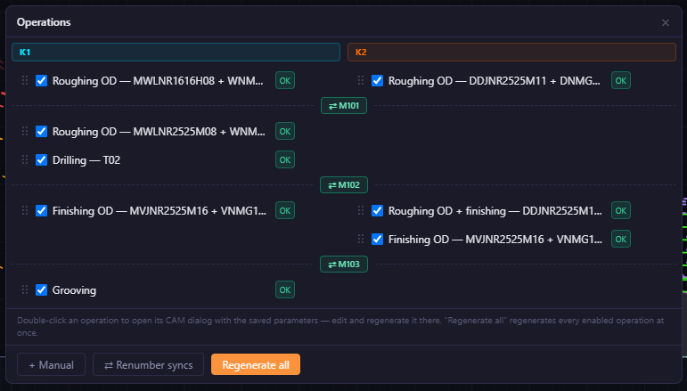
- K1 and K2 side by side. Both channels are shown in two columns, and the sync points (for example
M101) are drawn as bands across both of them. You can see at a glance what runs in parallel. - Order is changed by dragging an operation with the mouse.
- Switching off an operation removes it from the G-code; switching it on puts it back.
- Double-click opens the CAM dialog with the parameters the operation was created with. Change what you need and regenerate.
- Sync codes. Click a sync band to change its number;
⇄ Renumber syncsnumbers them in order. - Regenerate all recalculates every enabled operation at once, grooving and drilling included. Handy after changing the contour or the stock.
- Manual operations. Parts of the program you wrote by hand appear in the list too, so the list matches the whole program.
CAM quick menu
To the left of the canvas there is a new icon bar with the CAM operations, view toggles, the 3D view and the Setup Sheet — everything you need while working on a program, one click away. The CAM menu has also been reorganised, dialogs remember their position and the Snippet, Grooving and Drilling windows take up less space.
Break: ending a contour with a radial exit
Sometimes you only want to machine part of a DXF contour — for example up to a shoulder — and then take the tool straight out. Use Break in the contour selection toolbar:
- Click the point on the contour where machining should end.
- Enter the exit diameter, or pick it with the mouse.
- Choose whether to keep the start or the end of the contour.
- Confirm with Apply.
A preview shows the radial exit before you confirm it.
New G41/G42 engine
If you want programs with tool nose radius compensation, CAM now generates the toolpath on the nominal contour and switches G41/G42/G40 on and off at the right places. The passes are the same as in a G40 program, including No Dragging and the angled entry, so you don't lose any of the CAM features by switching to compensation. The output respects the rules of the selected control.
The simulator now calculates the compensation the same way the control does. For a G41/G42 program it computes the tool path from the programmed contour, so you see what the machine will actually cut — before the program gets to the machine.
Fixes
- Selecting Range on an already selected part of the contour no longer freezes the application.
- The 3D window adapts to smaller screens.
- Security improvements.